How Does a Servo Feeder Improve Stamping Accuracy
A quick overview of the topics covered in this article.
A stamping line can have a good press and a well-made die, yet still produce unstable parts if the material does not enter the die at the right position. Small feeding errors can quickly become scrap, rework, and lost material.
A servo feeder improves stamping accuracy by controlling feed length, preparing the coil before it reaches the die, and keeping material movement stable. In the Y02 system, servo feeding, 11 leveling rollers, anti-slip roller treatment, and photoelectric loop control work together to support repeatable feeding.
To understand why this matters, it helps to look at the feeding process step by step.
1. What Is Feeding Accuracy in a Stamping Line
Feeding accuracy is the ability to move the strip forward by the required distance again and again.
For example, if a die needs the strip to advance 120 mm for every press stroke, the feeder must deliver that distance as consistently as possible. A small error may not look serious on one stroke. After hundreds or thousands of cycles, however, it can affect part position, edge distance, and material use.
The Y02 system is designed for fixed-length feeding. Its stated repeat feed-distance accuracy is ±0.15 mm for feed lengths from 0 to 1000 mm. The machine also has an adjustable delivery height, which helps match the feeder with the press and die height.
Good feeding accuracy helps in several ways:
- Parts enter the die at a more stable position.
- Strip pitch remains more consistent.
- Material waste between parts can be better controlled.
- Continuous stamping becomes easier to manage.
- Operators need fewer manual corrections.
In other words, feeding accuracy is not only a feeder specification. It affects the stability of the whole stamping process.
2. How Does Servo Control Improve Feeding Accuracy?
A servo feeder uses a servo motor to control how far the material moves.
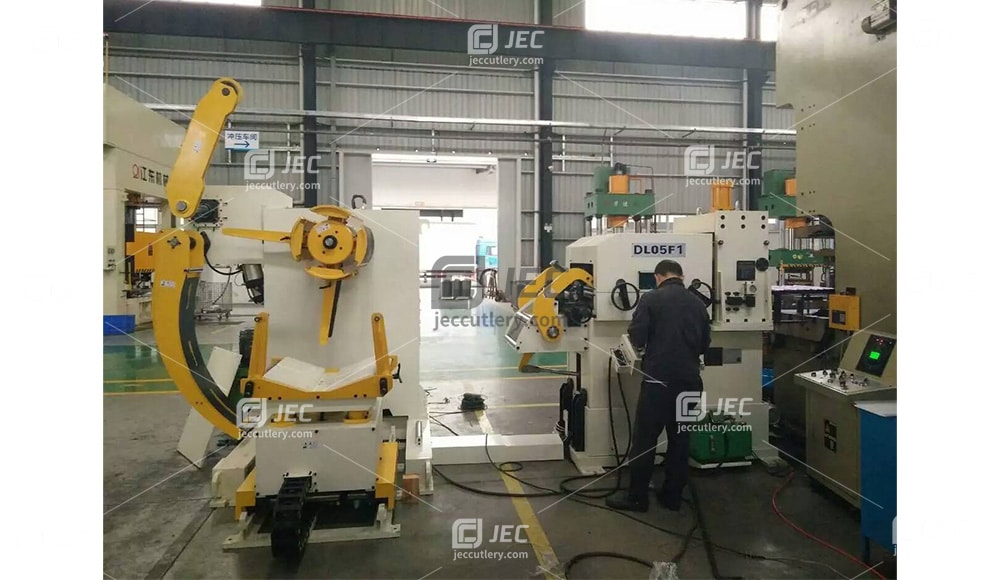
The Y02 leveling and feeding unit uses a servo motor drive for fixed-length feeding. This gives the control system a clear target for every feed cycle. Instead of relying only on mechanical movement, the system can control the feed length through the servo drive.
This is important because stamping lines do not always run at one feed length. A factory may produce several parts with different pitch requirements. Servo control makes it easier to change the feed value through the control system rather than making major mechanical adjustments.
The Y02 also uses a touchscreen control system with parameter memory. This is useful when the same product is produced again later. Operators can store and recall settings instead of rebuilding the process from zero each time.
Servo control is only one part of the solution, though. The motor may command an exact movement, but the material must still remain flat and must not slip. That is why leveling and roller grip are just as important.
3. Why Is Coil Leveling Important Before Feeding?
Coil material is naturally curved because it has been stored in a roll. After unwinding, the strip may still carry coil set and uneven curvature.
If this material goes directly into the die, the strip may not sit flat. That can affect feeding stability and the way the material enters the stamping area.
The Y02 combines leveling and feeding in the same section. It uses 11 leveling rollers: 6 upper rollers and 5 lower rollers. The leveling adjustment accuracy is listed as ±0.01 mm.
The rollers bend the strip in a controlled way as it passes through the machine. This helps reduce the remaining curve in the coil and prepares a flatter strip for the next step.
The basic process can be understood like this:
Coil → Unwinding → Leveling → Servo Feeding → Punch Press
Leveling does not replace accurate feeding. It supports it.
A servo feeder works best when the strip entering the feed rollers is already in a stable condition. If the material is badly curved, twisted, or under changing tension, even a precise servo system has more work to do.
This is one of the main reasons why a three-in-one system can be useful. Decoiling, leveling, and feeding are designed to work as one process rather than as three unrelated machines.
4. How Do Roller Grip and Loop Control Keep Feeding Stable?
A servo motor can move very accurately, but there is one simple problem that must be controlled: slippage.
If the feed rollers turn but the strip slips between them, the motor position may be correct while the actual material position is not.
The Y02 addresses this by treating the clamping roller surface with wire-surface sandblasting and hard chrome plating. According to the product specification, this treatment is used to increase friction between the roller and the material and reduce slipping during servo feeding.
Material tension also matters.
The decoiler should not pull against the feeder too strongly. At the same time, too much loose material between the machines can make feeding unstable.
The Y02 uses two sets of photoelectric switches to monitor the material arc between the decoiler and the leveling feeder. The sensors send feedback to control the start and stop of the decoiler spindle. This keeps a buffer loop between the two sections.
The working logic is simple:
Decoiler → Material Loop → Photoelectric Sensor → Leveling Feeder → Press
When the loop becomes too small, the decoiler can supply more material. When enough material is available, it can stop.
This helps prevent the feeder from constantly fighting the inertia of a heavy coil. It also gives the servo feeding section a more stable material supply.
For automatic stamping, this detail is easy to overlook. But stable feeding often depends on what happens before the strip reaches the feed rollers.
5. How Do Material Thickness and Strength Affect Feeding Performance?
One of the most important points in feeder selection is that maximum thickness alone does not tell the whole story.
The Y02 is specified for material thicknesses from 0.3 to 3.2 mm and widths from 50 to 400 mm. It can handle cold-rolled sheet, pickled sheet, galvanized sheet, and stainless steel sheet.
However, the correction-capacity table shows that the maximum usable width changes as material becomes thicker and stronger.
For thinner material, the machine can handle the full 400 mm width across the listed strength ranges. At greater thicknesses, the available width becomes smaller.
| Material Thickness | Max Width at 184 N/mm² | Max Width at 214 N/mm² | Max Width at 245 N/mm² |
|---|---|---|---|
| 2.0 mm | 400 mm | 400 mm | 400 mm |
| 2.2 mm | 396 mm | 345 mm | 300 mm |
| 2.5 mm | 303 mm | 264 mm | 230 mm |
| 3.0 mm | 185 mm | 161 mm | 140 mm |
| 3.2 mm | 145 mm | 126 mm | 110mm |
This table explains an important engineering point.
A feeder may be rated for 3.2 mm material, but that does not mean every 3.2 mm strip can be processed at 400 mm width.
Material thickness, width, and strength must be considered together.
This is especially important when working with stainless steel or other higher-strength strip. Before setting up a production line, the actual material properties should be matched with the correction-capacity range of the machine.
That approach is much more reliable than selecting equipment only from the headline figures of “maximum width” and “maximum thickness.”
Conclusion
Accurate stamping starts before the strip reaches the die.
Servo control provides repeatable feed length. Leveling prepares the coil. Proper roller grip reduces slipping, while loop control keeps material supply stable.
When these functions work together, the press receives material in a more controlled and repeatable way. That is the real value of an integrated servo leveling and feeding system.
A quick overview of the topics covered in this article.